
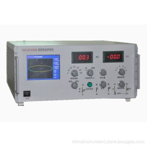
Gdjf-2008 Transformer Partial Discharge Detector
- Payment Type:
- L/C, T/T, Western Union, Paypal, Cash
Quantity:
Your message must be between 20 to 2000 characters
Contact NowBasic Info
Basic Info
| Place of Origin: | Chongqing, China |
|---|---|
| Payment Type: | L/C, T/T, Western Union, Paypal, Cash |
Product Description
Product Description
Introduction:
V GDJF-2008 Partial Discharge Detector is measuring partial discharge for the products such as transformers, mutual inductors, HV switches, zinc monoxide arresters and powercables. It also can make type tests and monitor insulation operation.
V This type has the advantages of high sensitivity, wide range of capacitance, being well equipped for input unit impedance detecting and more variants of frequency bands ( 9 in all). After proper setting, the discharge impulse amount can be read directly. The indicating and digital meters are shown simultaneously.
V This detector is widely applied in power stations, manufacturers and institutions.
Technical Specifications:
Use Condition:
V Ambient temperature: 0-40º C± 2º C.
V Relative humidity: ≤ 80%
V Power supply: 220V± 10%, 50Hz.
V No violent vibration and mechanical shock
V The device should be placed in the environment with no dust and corrosive, good ventilation. It should not be interfered by strong electromagnetic
V Earthing requirements: Earthing resistance <1Ω
Capacitance range to be tested 6PF-250μ F
Amplifier band
V Low terminal: 10kHz, 20 kHz, 40 kHz (optional)
V High terminal: 80 kHz, 200 kHz, 300 kHz (optional)
Amplifier gain adjustment
V Coarse control - there are 6 gears for coarse tuning, the gain of each gear is 20± 1db
V Fine control ≥ 20 db
Time windows
V Width of window, adjustable 15o— 150o
V Window position, adjustable 0o— 170o
V Two windows can be opened simultaneously or separately.
Discharge meter
V Digital display
V PD display: LED 3½ Digits
V 0-100.0 limit of error <± 3% (full scale)
Ellipse time base
V Frequency: 50Hz and arbitrary frequency
V Elliptic display color is yellow
V Elliptic rotation: Each gear is 30° , 180 ° Rotation can be made.
V Display: Ellipse - straight line
V High frequency time base elliptical input voltage less than 220 V, intake power < 1VA
Waveform lock
Lock required waveform of any time to facilitate observation and analysis
Testing Voltage meter
V Range: 100KV (Can be expanded)
V Display 31/2 digital voltage meter
V Accuracy: Better than ± 2% (full scale)
Inside, outside the zero mark function
Dimensions: 450× 450× 190 mm
Weight: About 16kg
Technical Specifications:
V The principle is based on ERA i. e high frequency pulse current measuring.
V When test object generates partial discharge under testing voltage, the discharge pulse
V signals is carried through coupling capacitors Ca into input unit, which gets pulse signals.
V After amplification of low noise through preamplifier, the required frequency band chosen by filter amplifier and the main amplifier (reaching the required amplitude and get zero-marked pulse), the discharge pulse can be seen on the ellipse of CRO, and the peak marker also displays on the meter.
V Time window controls the working time of pulse peak meter of testing voltage each week, and brightens the corresponding display area in the period of time, which can avoid the interference of the fixed phase.
V Test voltage meter produces, through capacitive voltage divider, test voltage zero marker signal, and displays zero marker pulse on CRO. The test voltage is displayed on digital voltage meter.
Related Keywords
Related Keywords
You May Also Like
You May Also Like
-
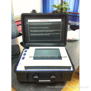
Gdva-405 Advanced Automatic Current Transformer CT and Voltage Transformer PT Tester
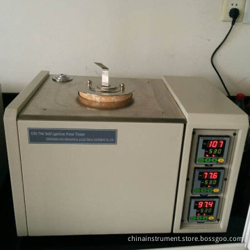
Gd-706 Petroleum Products Ignition Point Tester
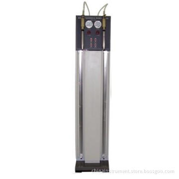
Liquid Petroleum Products Hydrocarbon Tester ASTM D1319
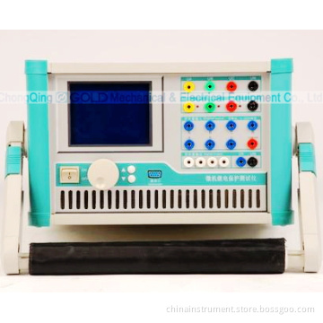
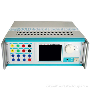
Gdjb-PC LCD Display Electrical Protection Relay Tester
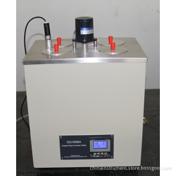
Gasoline Copper Strip Corrosiveness Tester ASTM D130
Related Products-
Gdyj-502 Insulating Oil Breakdown Voltage Tester
-
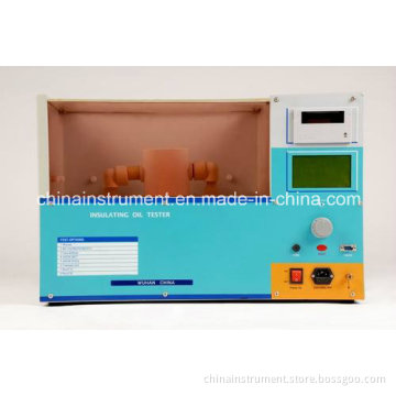
Gdyj-502 Fully Automatic Insulating Oil Dielectric Strength Tester
-
Gdjb-PC LCD Display Electrical Protection Relay Tester
-
Gdva-405 Advanced Automatic Current Transformer CT and Voltage Transformer PT Tester
-
Gdva-405 Fully-Automatic CT Analyzer for Testing All Parameters of CT